
The most commonly cited advantage of deploying IP video networks in production and other operational applications is the ability to use commercial off-the-shelf (COTS) IT-based infrastructure, which takes advantage of the economies of scale of the IT industry when compared with the relatively small broadcast industry. Additional advantages of reduced cabling cost and weight along with the much greater routing flexibility that offers more flexible production options. These advantages have captured the industry by storm and broadcasters are already working on early deployments of IP video networks. Not far behind deployment is the need to efficiently diagnose and resolve faults.
IP introduces new technical and skills challenges. These include jitter, latency and the risk of dropped packets and network asymmetry that results in different path delays upstream and downstream.
Deploying IP for video production applications is effectively the collision of the two worlds of video and network engineering. Video engineers are comfortable with the use of SDI, coaxial cable, patch panels, black burst and tri-level sync for timing and above all, monitoring signal quality. The challenge for the video engineer is to understand IT technologies and impact of an IT infrastructure on the video.
On the other hand, network engineers are familiar and comfortable with, IP flows, protocols, network traffic, router configuration, Precision Time Protocol (PTP) and Network Time Protocol (NTP) for timing. The biggest difference however is that in most data center applications, lost data can be re-sent – this is not the case with high bitrate video. The challenge for the network engineer is in understanding video technology and its impact on IT infrastructure.
Overcoming jitter
In any digital system, jitter is any deviation from the regular periodicity of the signal. In IP networks jitter is the variation of the packet arrival interval at a receiver. If the network routers and switches are all configured and operating correctly, the most common cause of jitter is network congestion at router/switcher interfaces.
The application within a network element will likely require the data to be received in a non-bursty form and as a result, receiving devices adopt a de-jitter buffer, with the application receiving the packets from the output of this buffer rather than directly. As illustrated in Figure 1, packets flow out of the buffer at a regular rate, smoothing out the variations in the timing of the packets flowing into the buffer.
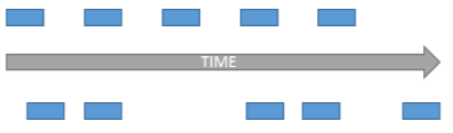
Figure 1. Packet jitter is deviation from the periodicity of the packet arrival interval.
The rate of packets flowing out of the de-jitter buffer is known as the “drain rate.” The rate at which the buffer receives data is known as the “fill rate.” If the buffer size is too small then if the drain rate exceeds the fill rate, then the buffer will eventually underflow, resulting in stalled packet flow. If the sink rate exceeds the drain rate, then eventually the buffer will overflow, resulting in packet loss. However, if the buffer size is too large, then the network element will introduce excessive latency.
Jitter can be measured by plotting the time-stamps of the packet inter-arrival times versus time as shown in Figure 2.
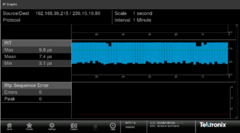
Figure 2. Packet inter-arrival intervals plotted versus time.
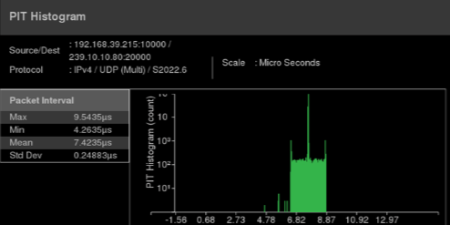
This is useful to identify variances in jitter over time, but it is also useful to be able to plot the distribution of inter-arrival intervals vs. frequency of occurrence as a histogram. If the jitter value is so large that it causes packets to be received out of the range of the de-jitter buffer, then the out-of-range packets are dropped. Being able to identify outliers such as the example in Figure 3 is an aid in identifying if the network jitter performance is either likely to or already the cause of packet loss.
Figure 3. Packet inter-arrival intervals plotted versus frequency of occurrence.
A series of packets with long inter-arrival intervals, will inevitably result in a corresponding burst of packets with short inter-arrival intervals. It is this burst of traffic, that can result in buffer overflow conditions and lost packets. This occurs if the sink rate exceeds the drain rate for a period of time that exceeds the length of the remaining buffer size, when represented in microseconds.
Establishing de-jitter buffer size
To establish the necessary de-jitter buffer size, an alternative form of jitter measurement known as delay factor (DF) is used. Delay factor is a temporal measurement indicating the temporal buffer size necessary to de-jitter the traffic.
In IP video networks, the media payload is transported over RTP (real-time protocol). One form of DF measurement takes advantage of the fact that the RTP header carries time-stamp information that reflects the sampling instant of the RTP data packet. This is known as time-stamped delay factor or TS-DF (as defined by EBU Tech 3337) and represents temporal buffer size in microseconds as shown in Figure 4.
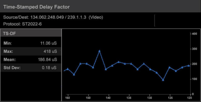
Figure 4. TS-DF represents temporal buffer size in microseconds.
The TS-DF measurement is based on the relative transit time, which is the difference between a packet’s RTP timestamp and the receiver’s clock at the time of arrival, measured in microseconds. The measurement period is 1 second, with the first packet at the start of the measurement period being considered to have no jitter and is used as a reference packet.
For each subsequent packet, the relative transit time between this packet and the reference packet is calculated and at the end of the measurement period, the maximum and minimum values are extracted and the Time-Stamped Delay Factor is calculated as:
TS-DF = D(Max) – D(Min)
Finding root causes
To establish root causes, it is necessary to understand whether visible impairments are being caused by IP errors or if some other fault is causing the impairment. Figure 5 shows how a network monitoring tool can be used to track time-correlated video and IP errors. This is made possible by correlating the time stamps of the video errors and the RTP packet errors.
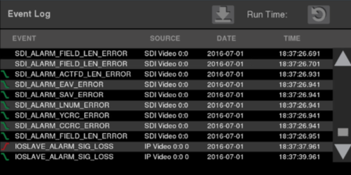
Figure 5. Time-correlated video and IP errors.
A video CRC error does not in itself confirm that the video is impaired making it desirable to use traditional monitoring methods such as picture and waveform displays as well as audio bars.
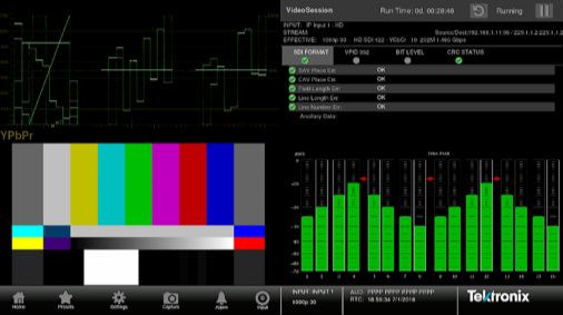
Figure 6. Traditional video monitoring and audio bars are useful in confirming errors.
Tracking PTP errors
Device clocks in IP video networks have no inherent concept of system time, so precision time protocol (PTP) is used to synchronise these clocks. The most recent version is IEEE 1588-2008, also known as PTP version 2 with the SMPTE ST 2059 PTP profile being specifically intended for broadcast applications.
In effect, PTP provides genlock functionality equivalent to that delivered by black burst or tri-level sync in SDI networks. The overall PTP network time server is referred to as a PTP grandmaster, with devices that derive their time from PTP being referred to as PTP Slaves. PTP grandmasters are usually synchronized to GPS, GLONASS or both.
For the foreseeable future, many video networks will use a combination of SDI and IP. To allow frame accurate switching between SDI and IP derived content, it is essential that the timing of the Black Burst/Tri-Level Sync is not offset relative to the PTP clock.
This is achieved by measuring the timing offset between the PTP clock and BB/Tri-Level Sync and then making any necessary correction by skewing the SDI syncs with reference to the PTP clock.
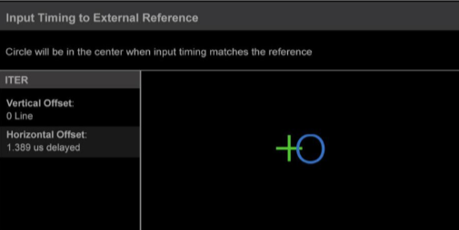
Figure 7. Measuring the time relationship between BB/Tri-Level and PTP.
A final consideration
In live production applications, network experts may not be present on the production site and networking equipment also may not necessarily be in a location that is easily accessible. It is desirable that network and video engineers can control any diagnostic equipment remotely.
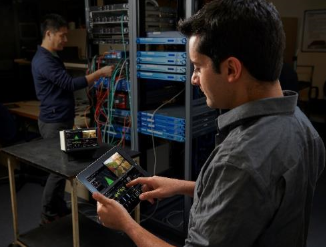
Figure 8. Remote control ability enables on-location access to network expertise
An all IP infrastructure is the vision for most broadcasters around the world and is already starting to happen in many facilities. The reality is however that the transition won’t happen overnight leading to the need to manage hybrid SDI and IP infrastructures, and thus a need for IP and video engineers to work closely together to ensure seamless operation and quickly track down faults.
# # #
Thought Gallery Channel:
Tech Talk