What exactly does 5G mean? And what are the implications of this new mobile technology for media businesses?
By SKIP PIZZI
[Reprinted from the September/October 2019 issue of The Financial Manager]
People like labels. Companies like labels. Industries like labels. In today’s complex world, they simplify things, and allow us to sort them into more easily understood categories.
So how much simpler could the label “5G” be? One number and one letter – a thing of beauty. But as Einstein famously said, “Everything should be made as simple as possible, but no simpler.” And that’s where the problems with understanding 5G begin.
The label is applied to a very wide range of technologies, and it is understood to mean different things by different people, companies and industries. That kind of confusion certainly has occurred for other forms of emerging technology. But in the case of 5G, the term has been leveraged by marketers for their particular purposes, and already co-opted into substantial hype and resulting misconceptions.
The value of the label 5G has been thereby diluted, and its value diminished rather than increased in helping us understand what the technology is, and what it means to the businesses that may use or be affected by it in the near future.
SO, WHAT IS 5G?
The origin of the term comes from the world of wireless technology standards, where it implies (as you might guess) the fifth generation of cellular phone technology. But as in the passage of previous generations of technologies, the boundaries between them are not hard and fast. (See “The Wireless Solution” below)
5G will replace 4G in two distinct phases. First, the introduction of 5G will prompt the rollout of new mobile software, because the new technology allows somewhat more efficient use of existing wireless bandwidth than 4G does. This is an incremental change, not unlike previous transitions between wireless technology generations.
This transition has already begun in some markets, and will continue over the next few years, as new mobile devices that support the technology become available.
But the second phase of 5G will truly open up new horizons, as it will allow far faster connections. This is mostly due to its use of wholly new, higher frequency operations – so-called “millimeter wave” (mmWave) bands – which allow wider bandwidth connections per user. Don’t expect to see this broadly deployed until the mid2020s, however. And even then, it will only be found in densely populated urban areas. Even 5G’s strongest champions agree that it’s unlikely mmWave 5G will ever be seen in rural areas.
Until now (i.e., through the 4G era), wireless phones have operated in various bands between 600 MHz and 6 GHz regions, but with the full deployment of 5G, frequency bands above 24 GHz (mmWave) will be used. That will allow users to connect to the network on much wider-bandwidth channels. As a result, full 5G deployment will provide consumer devices with connectivity up to 20 times faster than with 4G, while also increasing the capacity of simultaneous users per cell.
If this seems too good to be true, bear in mind that these higher transmission frequencies will necessarily limit the coverage zones for individual cells to much smaller areas. They may be as small as a few tens of meters in diameter per cell.
This means that the 5G mmWave deployments will require vast numbers of transmitters and antennas spaced closely together for the system to work practically for customers, which is why the full impact of 5G will only be felt in urban areas.
Notwithstanding the geographically limited nature of mmWave deployments, though, other benefits promised by 5G generally include:
Greater robustness, such as fewer dropped calls;
Low latency, for faster data transfer;
More sophisticated antenna design to allow more users to connect at higher speeds in a given area without interference;
Network slicing, which allows multiple forms of usage to share the network simultaneously, such as smartphones and Internet-of-things (IoT) devices;
Edge computing/virtualization, which puts cloud computing servers physically closer to customers, further reducing latency and reducing network congestion.
IMPACT ON MEDIA
Another 5G feature, which worries some in the traditional media businesses, is its so-called “broadcast mode.” This allows a one to-many delivery format akin to broadcast radio or television service.
Such capability already exists in the current 4G LTE system, but 5G further expands it. Yet even 5G’s broadcast mode is not infinitely scalable like traditional broadcasting has always been. Even if it was, the economics of the system do not appear likely to entice mobile network operators into entering the radio or television business.
However, one media sector that does seem particularly vulnerable to new competition from 5G is the multichannel video program distributor (MVPD) business. Some wireless operators are considering the use of 5G as a “last meter” (or “last tens of-meters”) delivery method for IP-based service bundles to the customer without stringing cable into the home.
5G’s wideband, wireless connection from the antenna on the street pole to the homes on the block (or to the multiple units of an apartment building) are an appealing and potentially cost-effective alternative to traditional hard-wired fiber or coax – or even small-dish satellite – delivery of television and/or broadband Internet service to residential customers. So some 5G effects may be felt by traditional fixed (i.e., wired) rather than mobile operations. Or, put another way, 5G offers wireless operators new ways to compete with traditional wired telecom businesses.
Nevertheless, the net result of 5G’s impact on existing media businesses may be ultimately beneficial, as traditional operators find ways to use 5G services to improve operations. For example, content creators will benefit from enhanced connectivity for live backhaul of content from remote sites, while weather forecasters and other data-collectors can deploy massive numbers of sensors using IoT devices for accelerating their services.
Crowdsourcing of content or audience interaction also could be boosted by the increased capacity and speed of 5G. Yet another possibility is convergence with the similarly IP-based ATSC 3.0 system soon expected to be deployed by television broadcasters, by which broadcast transmission and wireless broadband service can be used together and simultaneously to provide rich and responsive media experiences to tomorrow’s audiences.
Yes, there’s a lot to like – and some to worry – about 5G among media businesses. The best advice now is to avoid the hype and continue to study the real prospects for the technology, to learn how it can best work with, or against, your existing services.
THE WIRELESS SOLUTION Most of us have already experienced transitions between generations of modern mobile telephony. It seems almost miraculous how the world of cellular phones has evolved so quickly over the mere four decades in which it has existed. But there’s no magic to the evolution – just good standards and practices by the industry.There are international standards bodies that continually work to allow wireless services to develop at a relatively fast pace. Among them is the International Telecommunications Union, a part of the United Nations that manages and resolves the use of different telecommunications methods used in different countries and regions. Another is the 3rd Generation Partnership Project (3GPP), which develops international standards for interoperable mobile broadband software and hardware.3GPP has developed an approach called long-term evolution, which expects new releases of backward-compatible mobile telephony standards to be issued on a regular basis. This means that wireless network operators can support multiple generations of consumer equipment simultaneously over periods of time.For example, when the industry moved from 3G to 4G, there was no mystical night during which everyone’s phones upgraded. People’s older phones continued to work like they used to, even as new technology was deployed by carriers. At the same time, customers who purchased new phones could enjoy the benefits of the latest services. Wireless operators maintain and continue to support the legacy generation of technology for a long period of time after they begin to deploy the next generation of technology. This also means that wireless operators require adequate spectrum to operate multiple, parallel systems during any transition between technology generations.And of course, the Internet – to which wireless phones allow mobile connectivity – also evolves in an elegant fashion, as managed by the standards of the Internet Engineering Task Force and the World Wide Web Consortium. Ideally, customers never notice these evolutions, since their old phones continue to work until they replace them with new phones, which then work better. What customers don’t recognize is that their new phones may be connecting to a different network than their old phones did, even though they are still using the same wireless provider’s services. This quiet evolution is designed to theoretically continue indefinitely.
Skip Pizzi is vice president of technology education and outreach at the National Association of Broadcasters. He can be reached at Spizzi@nab.org.
OTT and video streaming are here to stay. Millennials are
increasingly watching content on their mobile devices and computers and a
71% growth in viewership has been observed since 2012. However,
watching video on mobile devices is not limited to the youth. In the US,
86% of smartphone users watch video content on their phones. [1]
Broadcasters need to brace up for the changing viewing styles by
embracing Over-The-Top (OTT) workflows, which threatens to take the
center stage if the viewing patterns are any indication. Ensuring right
delivery of technically sound content is critical for every broadcaster.
The right set of Quality Control tools are a must to ensure that you
stay ahead in the OTT race.
The Changing Face of Media Delivery
The traditional broadcast delivery is a linear flow with content
being pushed downstream to set top boxes on the consumer side. The
channel of delivery may be cable or satellite, DTH or IP network. The
delivery format is singular and resolutions are SD, HD or UHD. Users
view the content on their TV sets. But this mode of programming has been
rapidly changing. Viewers are increasingly shifting to watch content
when they want, where they want and on the device they want. Content
needs to be streamed as per user requirements, on demand and as per the
resolution of the playing device. The content is now being pulled by the
consumers as per their needs. Broadcasters need to ready their content
for this mode of playback – they don’t control the delivery, consumer
does. Welcome OTT!
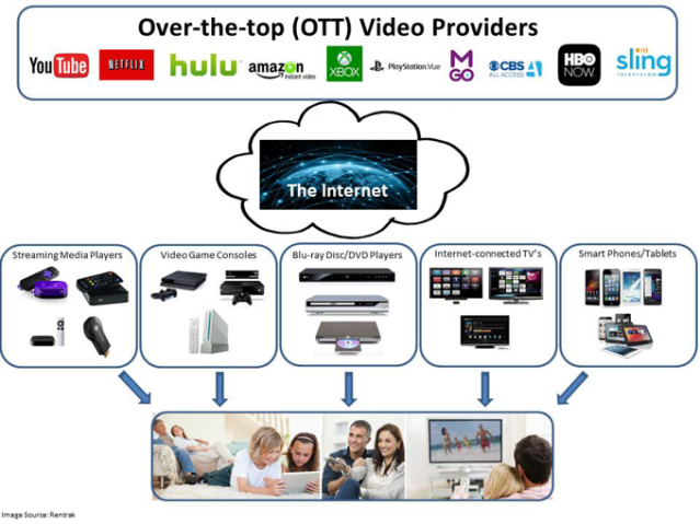
What is OTT?
OTT uses the Internet to bring audio-video content to the consumer.
As opposed to traditional video distribution methods, which operate
under a dedicated and controlled network, OTT video uses the Internet,
which is an unmanaged network, used across the globe by millions of
people. OTT content from broadcasters and video service providers
typically include streaming of content such as TV programs, movies, live
sports, and other special events. YouTube videos are also a prime
example of OTT video. Other OTT providers include Amazon, Netflix, Hulu,
etc.
To enable OTT deliveries, broadcasters need to embrace multiple
technologies, more complex than the traditional linear flow – a delivery
where the content is repurposed based on the user device, the
quality/bandwidth of the delivery is changed based on the network
congestion, and the content is not broadcasted to multitudes, but pulled
by individual consumers. This is achieved using adaptive bit-rate (ABR)
technology.
What is ABR?
With ABR, multiple versions of a video are created – each version
encoded at a different bit rate and profile. Each of these versions is
further broken into short-duration segment, which is aligned with the
same segment in other versions. Depending on the network bandwidth
available on the consumer device, an appropriate segment from a specific
file is sent to the user. This assures that the user receives the best
quality video in an uninterrupted manner.
Different wrapper formats have emerged for ABR technology, the most
popular ones being HLS, DASH and HSS. Different devices consume
different streaming formats, for example, Android and iOS devices
consume HLS (now a universal streaming format), Microsoft XBOX, Windows8
phones can consume HLS / HSS and so on. For a broadcaster, embracing
these multiple OTT formats over and above the linear flow has suddenly
made their life a lot more complex. And amid this complexity, one is
still struggling to cost effectively provide streaming option in
addition to traditional deliveries.
OTT workflow – Video-on-Demand (VOD) vs. Live Streams
For the purpose of this document, we would like to distinguish OTT
workflows based on whether we are talking about stored program content
or live programming. Stored programs are managed using file-based
workflows typically as VOD assets. Here, the broadcaster has the time
and luxury to ensure quality of assets during the content preparation
stage using file-based QC tools. BATON® ABR, as discussed later, serves
the need very well at this stage. However, in the case of live-streams,
content is transcoded in real-time into the chosen ABR formats and made
available for streaming. In both the cases, any delivery issues with
real-time streaming are verified using real-time OTT content monitoring
tools like ORION™-OTT, discussed later in this document. The next
sections discuss the QC and monitoring needs for both the workflows in
further details.
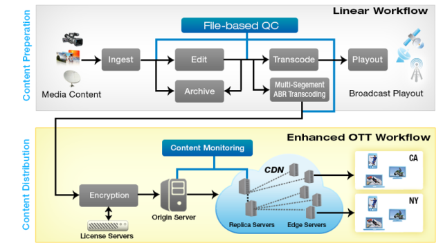
QC & MONITORING for VOD assets in OTT workflow
To be able to effectively monetize OTT for VOD assets, the media
companies need a unified QC & monitoring solution, as shown in Fig.
1, for content preparation as well as content distribution to ensure
good experience for viewers in the OTT/ABR world.
Figure 1. Typical Broadcast Workflow Enhanced with the OTT Delivery Flows
Next, let us look at the QC needs during the content preparation
stage, and the monitoring during the content distribution stage.
QC DURING CONTENT PREPARATION
You need to ensure that the quality of original content is good. At
the content preparation stage, file-based QC solutions like Interra
Systems’ BATON® helps you to address quality challenges, quite
comfortably. From ingest to editing issues, compression artifacts
introduced during transcoding, as well as file assembly issues – most
are easily identified by the modern QC tools.
You must deploy the right QC tools that match your quality needs for
the content preparation stage to mitigate your risks and ensure that
technically sound content is ready for delivery.
The QC checks can be broadly classified as follows:
Baseband Quality Checks
It is important to ensure that the content is checked on various
quality parameters before the final delivery. A comprehensive QC tool
needs to be used for a wide range of baseband quality checks, such as
video signal levels, color bleeding, blotches, blur, defective pixels,
black frames, color bars, RGB color gamut, mosquito noise, audio levels,
audio noise and a host of other such artifacts. Good QC tool must
ensure that these are detected with high level of accuracy and
reliability and minimal false positives.
Chroma Phase Error
Compression Artifacts
When the content is compressed, several compression artifacts like
blockiness, pixelation, Moire pattern, ringing artifacts, and more can
get introduced in the lossy compressed video. A good QC tool needs to
ensure that the transcoded content is free from these artifacts.
File Integrity and Standards Compliance Checks
The file integrity and compliance checks ensure that the file or
content being delivered is not corrupt and has been encoded as per the
standard to ensure that the downstream tools are able to play it without
issues. This becomes even more important in the OTT context, where
there are a host of devices with different form factors and players from
multitude of vendors – and the content is expected to play well on all
of those devices.
Multi-Segment ABR Transcoding
Once master/mezzanine content has been verified using a file-based QC
solution, it can be subsequently submitted for ABR transcoding. ABR
transcoding is a complex process involving creation of multiple
renditions of the same content at different quality levels/bitrates. The
transcoding process is not only time consuming but also needs to ensure
proper alignment between different variants and rightful segmentation
of each variant. Failure to achieve this would result in playback issues
leading to revenue loss. That’s where different file-based QC &
monitoring and systems come into the picture. These tools can check for
ABR specific issues and alarm user before ABR package goes out for
delivery.
OTT delivery, as discussed earlier, deploys the ABR technology. ABR
requires content to be split into short segments of typically 10 seconds
each. This ensures seamless and fast switching between different
variants. Typically each ABR package is encoded at multiple bitrates
(typically three or more). When the content is played, the streamed
content switches between different bitrates as it moves to the next
chunk, managed using the manifest file and depending on the network
congestion and other factors influencing delivery quality.
When content is transcoded for ABR playback, several additional
checks need to be done on the transcoded content to ensure that the
content is ABR ready. Some of those checks are listed below:
Checks to ensure each segment starts with an independent frame. This
is to ensure that any chunk does not have any decoding dependency on the
previous one, so that during playback, a seamless switch can happen
when moving from one chunk to another.
Checks to ensure that all variants of the content are properly
aligned in terms of number of segments, segment duration, total duration
and content structure. A client can choose to playback a particular
variant depending on the download bandwidth available and device screen
size, therefore, it is imperative to ensure that all the variants are
consistent with each other and allow seamless switching across all of
the available variants.
Ensure consistency between metadata and actual content properties.
A client uses the metadata in the manifest files to choose the best
playback quality. If there is any inconsistency between the metadata and
the actual media properties, it may lead to playback issues and hence a
bad user experience.
Once the content is validated on these checks, it is ready for
delivery, both for linear as well as OTT flows. The content is encrypted
with one or more DRM technologies before it is moved to the origin
server for OTT delivery.
A good file-based QC solution should have capability to perform all
of the above ABR checks and also do a deep analysis to identify any
baseband issue. Once the content moves to the distribution stage, the
focus shifts to ensuring a smooth content delivery and the best possible
user experience. This creates a need for state-of-the-art monitoring
solutions that can ensure a superior QoS as well as baseline QoE. The
next section talks about the monitoring requirements in detail.
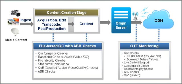
MONITORING DURING CONTENT DISTRIBUTION for VOD Assets
At this stage, we need to ensure that no issues will be encountered
during delivery of VOD content – in short ensure QoS as well as QoE. The
monitoring requirement at this stage is to perform real-time streaming
validations. There is some overlap with the File-QC done during the
content preparation stage, and that is necessary to ensure the content
sanity as it is replicated from the origin server to cache/replica
servers in a typical distribution or Content Distribution Network (CDN)
environment. However, the accuracy and details of file-based QC are not
needed at this stage. It is sufficient to do limited QC which is
significantly faster. Monitoring tools at this stage need to ensure the
following:
The content manifest should be accessible over HTTP/HTTPS and all the
references to profile manifests and individual segments should be
accessible
Ensure that the content is properly conditioned for ABR (refer to ABR checks in the previous section)
Server responds fast enough to ensure that content is downloaded within
acceptable delays and buffering needs -this can have a major impact on
the playback experience for a user
Content downloads are simulated in network congestion environment to
observe how the distribution server behaves under stress conditions
The content may also be decrypted at this stage to ensure that no issues were introduced during encryption
Basic audio-video quality checks (for example, blockiness, black frame, audio loudness etc.)
Passive monitoring of all the requests/responses for actual clients accessing the content
All HTTP response codes – 3xx,4xx,5xx should be monitored and logged
Several OTT monitoring solutions have emerged in the market. The OTT
technology is still evolving and the requirements for what is needed for
a monitoring solution at this point are also evolving. The monitoring
tools need to be architecturally versatile to accommodate this evolving
environment, while broadcasters figure out which issues are the most
critical ones to focus on. The ideal scenario for VOD based assets is
the one where OTT monitoring leverages the file-based QC tool, working
in tandem and seamlessly with it. The Fig 2 below illustrates how a
complete QC & monitoring solution works from ingest to delivery in
the OTT world.
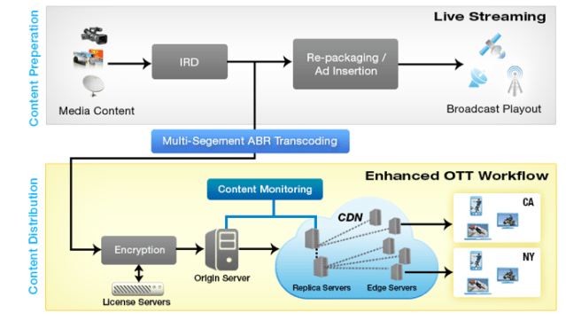
The typical live stream workflow enhanced for OTT deliveries is shown
below in Fig. 3. The live stream is split into segments, and as
segments are received, they are transcoded in real-time to the desired
ABR format. The segments are encrypted using any of the popular DRM
technologies and placed for consumption real-time on the origin servers.
More segments get added while the older ones get removed. The process
continues through the duration of the live content.
As evident, a full file-based QC does not play a role here. However, we still need to ensure the following:
Basic baseband checks are done. The segments that the live content is chopped into is free from basic baseband quality issues
ABR transcoding is happening properly. ABR segments are “good”, complying with the ABR specs to ensure seamless delivery
Timing and the load is well managed. ABR segments are made available at
the right time on the servers, and the servers are able to manage the
load
Essentially, on the live content, we need to perform basic segment
integrity and content quality checks, ABR transcoding checks and file
download checks. In short, ensure QoS and baseline QoE checks on the
growing content. These checks are performed using content monitoring
tools like ORION-OTT, similar to the VOD flow.
Figure 3: Monitoring for Live Streams in OTT Workflow
QC & MONITORING solutions for ott Enhanced workflows
Interra Systems provides end-to-end seamless and versatile solutions
for software-based content verification, monitoring, and analysis
solutions for file-based and real-time workflows in the digital media
industry.
To ensure the quality of original content for VOD assets, Interra
Systems’ BATON® ABR identifies quality issues from ingest to editing,
compression artifacts, as well as file assembly issues. Once the content
is validated with BATON ABR, it is ready for OTT delivery. Real-time
streaming validations, both for VOD assets and live streams, are done
with Interra Systems’ ORION™ – OTT.
Conclusion
OTT technology is still evolving, and the requirements for monitoring
are also changing. Monitoring tools need to be architecturally
versatile in order to accommodate this environment and allow
broadcasters to figure out which issues are the most critical ones to
focus on. Ultimately, broadcasters should choose an OTT monitoring
solution for Live and VOD assets that works in tandem with a file-based
QC tool. By deploying a complete QC and monitoring solution for ingest
to delivery, broadcasters can deliver the best QoS and QoE to viewers in
the OTT world.
[1] Ericsson: TV AND MEDIA 2015|The empowered TV and media consumer’s influence
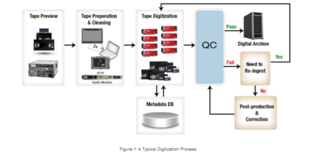
Over
the years, the broadcast industry has shifted from tape-based to
file-based workflows in an effort to increase operational efficiencies
and reduce overall expenditures. Since that transition, file-based
automated content QC solutions have emerged as the ideal method for
ensuring superior content quality, providing increased cost savings and
reliability over the traditional approach of visual inspection.
Yet, over the last decade, file-based media workflows have become
much more sophisticated, putting tremendous pressure on broadcasters
when it comes to ensuring content quality. While broadcasters used to
get away with supporting a simple QC model of checking a file, reviewing
its verification report, taking necessary actions, and then forgetting
about the issue, this approach is no longer effective for long-term
planning of content QC processes and making strategic changes.
Broadcasters need advanced tools that give a more holistic view and
deeper insights about how the content QC has happened over a long period
of time and across different departments and sites.
This article describes a Measure, Analyze, Optimize (MAO) framework
for incorporating data analytics in content QC processes. In addition to
describing the benefits of this framework, the article will examine
different use cases that illustrate how to get the best out of content
QC.
When content QC solutions are used continuously, a large amount of QC
data is generated. By analyzing this data, broadcasters can identify
trends and gain a deeper understanding of content quality across the
organization. These insights can help broadcasters make strategic
improvements in the content QC processes and achieve greater
organizational efficiencies.
The best framework for analyzing QC data is the MAO framework. The
MAO framework is a three-stage process that starts out by tracking
important QC performance metrics over the long term. Next comes
analysis. During this phase, the metrics are analyzed to identify common
patterns and operational issues; the analysis sheds light on areas of
improvement and suggests required changes. For the optimization stage,
those changes are applied to the content QC processes.
The cycle is then repeated. Using a file-based QC solution,
broadcasters will take a second measurement, verifying that the applied
changes have led to improvements in different QC performance metrics.
New measurements are analyzed for additional issues and required
changes.
The following sections will look at concrete examples of ways the MAO framework can be applied to improve content QC processes.
Asset Categorization
Broadcasters today are handling a huge number of assets. With so many
files at their disposal, most broadcasters only have a vague idea of
what types of assets they’ve acquired or created over the years.
Cataloging all of the assets can be a time-consuming and expensive
process. Whether or not a content management system (CMS) is being
utilized, all assets usually pass through some level of QC.
QC reports contain a wealth of metadata information as well as error
information about the files. The database where QC reports are stored
can be exploited to analyze and categorize the assets. For instance,
broadcasters can determine how many hours of content have been
processed, what bit rates are being used, and which assets are HD files.
When transitioning from SD to HD, categorizing assets can be
extremely useful, as it will give broadcasters an understanding of how
much legacy content still exists. Figure 1 shows that a total number of
38,864 files had undergone QC. The files contained 24 different values
of resolution. The most common resolution was 625(SD). About 60 percent
of files were encoded at this resolution. The second most common value
was 1080(HD), which covered about another 34 percent of files. There was
one odd file with a resolution of 528×480. Since there is a
significant amount of SD assets, the broadcast organization may decide
in this case that maintaining an SD-to-HD upconversion workflow is
necessary.
Figure 1. Resolution of different files
QC Results Summarization
Performing an in-depth analysis of QC results is crucial for
understanding the content QC process and ultimately reducing the number
of files that are failing. For example, broadcasters can look at what
percentage of files are failing due to an error, the different kinds of
errors present in various files, and which errors are more prominent
than others.
By digging deeper in the data, broadcasters can see how the failure
rate is changing over time. Figure 2 shows how the number of tasks is
changing from month to month based on success, failure, or warnings. In
this particular example, there isn’t much improvement in the failure
rate with time.
Figure 2. Month wise variation in success and failures
Looking at this data, broadcasters can identify the reasons why the
failure rate is not improving with time. Once the reasons have been
identified, the next step is to carry out the operational improvements
and achieve decreasing failure rates.
There are several ways to reduce the failure rate data. One option is
to restrict failures to specific watch folders to identify folders that
have more problems. Alternatively, broadcasters can look at the same
data for different types of content separately (e.g., HD vs. SD
content). If the broadcaster is operating stations in multiple
geographic locations, gaining insight into which site tends to have more
failures compared with others can be valuable.
Broadcasters can also decrease the failure rate data by analyzing
certain parameters like test plans, watch folders, content locations,
checkers, etc. (See Figure 3.)
Figure 3. Task results by different criteria
Taking a look at the watch folders in Figure 3, it’s clear that the
“Stories” watch folder seems to have a higher failure rate than others.
Furthermore, the “SD Open Stories Test Plan” tends to have more failures
than other test plans. These data points give broadcasters a clear plan
of action with regards to where to focus attention to improve content
quality.
The checker wise distribution is more useful for seeing if QC tasks
are evenly distributed across different checkers. In this particular
example it seems that two checkers are overloaded and are handling most
of the tasks.
Another way to approach QC results is to look at the most common
errors found across all tasks. In this case, broadcasters are advised to
look at the files with specific problems in detail and identify if
there are common causes in the workflow causing the problem in so many
files. It’s important to note that sometimes this data may not be
sufficient. Specific errors may be happening in fewer files but the
number of occurrences of the error in those files is very high.
Capacity Planning
In order to have an efficient QC process, broadcasters must ensure
that the QC system is lean and mean. There are several ways to address
this:
Checkers shouldn’t be sitting idle.
QC tasks should be completed in a reasonable amount of time.
Higher priority tasks should be given resources accordingly.
Create enough capacity to handle peak load situations.
In the case of multi-site QC systems, the resources should be equitably distributed.
A regular review of distribution of resources and their usage should take place.
Figure 4. Core Utilization and Task Queue
Broadcasters can increase the average performance index by allocating
more cores per task, disabling non-essential checks from the test plan,
and/or ensuring faster access to content from checkers. While using
more CPUs for the QC task may seem appealing, it doesn’t improve
performance proportionally. Furthermore, while increasing the
performance index may reduce the QC time, the system may be sitting idle
if there is not enough content to be processed all the time. Adding
more checkers to a QC system is expensive. Broadcasters will want to
find a good balance between the need to get QC done fast and ensuring
that the QC system is reasonably utilized all the time. In this
context, it is useful to divide the performance data according to
various parameters. For instance, broadcasters may want to look at
performance index for SD/HD/4K/8K files separately. This helps to decide
which files require more cores to achieve better overall performance
Each check in a test plan adds to overall QC time. In particular,
video/audio quality checks add significantly to the QC time. Reviewing
the test plan QC results, broadcasters can determine which checks never
fail in a particular workflow. Some of these checks may be required from
a regulatory compliance perspective and should never be switched off.
But others can be disabled altogether.
Sometimes different departments of the same broadcast organization
purchase independent copies of QC systems. In the case of multiple
offices in different locations, having independent QC systems cannot be
avoided. The analytics system can import data from these different
installations and provide a combined top level overview for strategic
planning.
Conclusion
The Holy Grail for broadcasters is to provide an immersive and seamless television experience to viewers on every screen. As the content lifecycle continues to grow in the future, with broadcasters contributing and distributing content in new ways, having a structured and automated content QC approach that leverages analytics will become an even more essential part of modern file-based media workflows, ensuring broadcasters can deliver high-quality content.
Reports have emerged (the best summary appears on Multichannel News,
“Group to FCC: Avoid ‘Walled Garden’ Approach to Video”) that both sides
are unhappy with the progress of STELA. The debate comes down to this:
Service providers want the ability to control the look and feel
(menus, recommendations, integration of live, VOD and DVR, etc.) around
their services.
CE manufacturers want the ability to integrate content from multiple
services (Pay TV, Netflix, YouTube, etc.) in order to give consumers a
unique and highly integrated experience.
As background, The FCC mandate limits the scope to “downloadable
conditional access” to enable retail products to play content from
service provider services. Of course, this narrow scope replaces the
physical Cablecard standard, which broke open the gates of competition
in the set-top box market, away from the duopoly of Cisco (formerly
Scientific Atlanta) and Motorola (then General Instruments, and now
ARRIS) to allow players including Humax, Samsung, and Pace into the
market. It also paved the way for retail TiVo boxes (despite technical
challenges around tuning adapters for switched digital video
implementations), although the set-top free household never emerged, as
only one or two models of TV ever included a CableCard slot.
In one sense, a replacement has already emerged for service provider
delivery to retail devices, based on the FCC definition of an “IP
output”. The FCC writes that boxes “shall comply with an open industry
standard that provides for audiovisual communications including service
discovery, video transport, and remote control command pass-through
standards for home networking.” For background, please read an earlier
ABI Research insight on CVP-2, now VidiPath. This standard, which is
embodied by DLNA’s VidiPath technology (DirecTV’s RVU also likely meets
the definition). Note that we conducted a webinar for DLNA on VidiPath.
This standard delivers a remote UI from a set-top box to a retail
device, as well as delivering video using DTCP-IP standards within the
home.
Against a Backdrop of a Competitive Environment
Overall, it is clear that there is significant innovation and choice
within the consumer video landscape. Significant, new, differentiated
services are being launched on a nearly monthly basis, including Dish’s
Sling TV, Sony’s Vue, HBO Now, a new Showtime service, etc. In addition,
traditional Pay TV providers are developing thinner and thinner
packages (litigating with content providers over them) for “cord
cutters,” with better economics than have traditionally been available
for Pay TV. Consumers now have excellent choices of subscription VOD,
transactional (rental and purchases) movies and TV, and ad supported
content.
Interestingly, a number of dynamics have emerged in the over the top
(OTT) world of Netflix, Amazon Instant Video, and iTunes that, we
believe, will favor the service provider positioning over the CE OEM
positioning. Specifically, it is clear that service providers have the
capability to choose the devices, locations, and content they make
available. Netflix has chosen a penetration strategy, aiming to be on
every internet connected device with a screen, while Apple has been more
judicious, favoring Apple products as well as PC’s (through iTunes).
Apple generally allows competing subscription services through the
iTunes App Store (Amazon Prime Instant Video, Hulu Plus), but unless the
service provider will offer revenue share for the rentals, Apple
politely declines the opportunity.
Finally, at times Netflix has made its catalog available via APIs –
allowing other services to “index” the Netflix catalog. Currently, based
on our understanding, those APIs are only available to companies with a
specific licensing agreement with Netflix (i.e. Roku has an agreement
to include Netflix results in universal search). Of course, this allows
service providers to define their business intent (allow traffic to the
service while not being devalued to a content provider as opposed to an
experience provider), and evaluate each opportunity on its own merits.
There are technical wheels at work here too – developments toward
universal content IDs (which could point to a show, a season, or an
episode) make content more universally accessible. However, companies
that have that linked up in a database (such as Rovi and Gracenote /
TMS) will typically only provide it under license with a service
provider, such as Netflix. Further, encryption of URLs is one of many
obfuscation techniques in use to make it harder to scrape service
catalog details.
Statutory Revenue Share, Negotiated Revenue Share and Partnership
The minimal arrangement that the STELA group could do is basically to
endorse a variation of the HTML5 EME / MSE extensions. This would
essentially allow service providers to choose a DRM provider and deliver
content securely to any device which met their criteria. Tuning of
modern set-top boxes and modern Pay TV services can be done only within a
closed system, or by leveraging a standard such as VidiPath. These
services have a mix of live content (well indexed by metadata
providers), DVR content, VOD content, and interactive ads, all of which
are delivered over a mix of relatively fixed location yet encrypted
channels, switched digital video channels which are delivered on demand,
and IP delivered channels.
As we discussed in the Netflix-Roku case, as well as Amazon’s
decision about what services to deliver on an iPad through the App
Store, negotiated revenue sharing is a business relationship well
understood and within control of the service providers and device
manufacturers.
Based on our belief that service providers’ ability to control the
integration and delivery of their experience will be held up by the FCC
and STELA commission, another solution to the impasse would be to
develop statutory licensing rates. This would allow, for instance, a new
CE manufacturer to deliver a service composed of a mix of HBO, ESPN,
and ABC content with highly personalized menus. It would do so based on a
rate table that determines the rates at which a wholesaler could
aggregate content. Of course, negotiated license rates would be better –
but it could provide a starting point for new services. This would
provide the entry into a new wholesale arrangement, but may occur at the
expense of control of exclusively licensed content.
Copyright Allied Business Intelligence, Inc. All Rights Reserved. This document is protected by US and International Copyright Law. No part of this document may be republished or entered into an information storage / retrieval system or database of any kind without the expressed written permission of ABI Research. This article was contributed to NAB Thought Gallery for posting by ABI Research.
For
many years, the pace of change in mass market IT has dwarfed that of
broadcast technology. For example, consumer camera phone resolution has
increased over the last ten years by 30,000%. In comparison, broadcast
resolution has barely tripled. With the development costs of consumer
cameras amortised over hundreds of millions of units, there is no way
that the broadcast industry can compete on the pace of progress. Nor
should it try to.
But in post production, large parts of the existing IT
infrastructures are exactly those which benefit most from the latest
revolutions in mass market IT. Computer processing power, storage, and
Internet access, all fuelled by mass-market consumer demand, are exactly
the features offered by cloud solutions.
As new technology enables more and more of the broadcast workflow to
move into the cloud, little more than a modest computer with an Internet
connection is needed to be able to create there. Processor speed, file
sizes and security, long regarded as significant barriers to cloud-based
workflows, are no longer issues. Instead of transitioning to newer and
newer generations of broadcast hardware, we’re moving from one IT
solution to another, saving significant costs.
What Makes the Cloud Suited for Post-Production?
Just as large-scale suppliers provide electricity more economically,
processing and storage requirements can often be met more economically
by cloud services. And just as electricity comes to us directly via
connection to a power grid, data comes directly to a computer via
connection to the Internet. In addition, cloud services from different
providers can easily interact through automated interfaces, providing a
highly flexible way of using solutions and add-ons from different
suppliers throughout a given workflow.
However, when it comes to video post-production, cloud services are
not all equal. Generic cloud-computing providers, such as Amazon Web
Services, are built for IT and consumer data rather than the voluminous
data and throughput performance requirements associated with broadcast
video. The requirements for editing video are formidable, with huge
amounts of data and the need for real-time responses. The process of
rendering effects and transitions in a generic cloud environment are
expensive since these services charge according to CPU power and time
used, and any unresponsiveness would be frustrating for users accustomed
to dedicated desktop solutions. When all of this is taken into account,
building a broadcast post-production operation on a generic cloud
infrastructure simply doesn’t meet broadcast standards for performance,
cost, or reliability.
Dedicated platforms optimised for broadcast applications offer lower
cost and far greater performance. They also provide increased control
over where the data is stored for legal, regulatory, and personal
preference requirements. The ease of switching between cloud providers
means that the availability of a single broadcast-ready cloud will, over
time, eliminate poorly performing alternatives.
Capacity and Efficiency
The capacity of the Internet and cloud services is essentially
unlimited, with supply expanding to meet demand. Storage and Internet
speed nearly double every year, and new solutions from the world of
mobile are improving power consumption within the cloud. With 10 Gb/s
intranet backbones in service now, throughput will continue to improve
drastically.
The greatest efficiencies come from leveraging client computing to
undertake as much of the processing workload as possible. Though it
might sound odd coming from a provider of cloud solutions, such a
scenario provides immediate scalability, reduces latency to negligible
levels, cuts costs and allows access with even the most modest of
hardware set-ups.
Better Picture Quality
The cloud is well suited to the post-production convention of working
with proxies, a method that, at least for the foreseeable future, will
be more efficient than working with high-resolution content. Proxies are
continuing to improve in both quality and resolution, with, for
example, higher resolutions provided for fine-cut editing than for
logging. Conforming from original HD sources ensures minimal generation
loss on the final output.
Many are already making 4K home videos in the cloud aided largely by
the fact that connection speeds have doubled every year while storage
costs have halved. As these factors continue to improve, the cloud will
look more and more attractive as an alternative in a wide range of
post-production workflows.
Technology has made post-production in the cloud easy. Now the focus
is on improving and perfecting reliability, responsiveness, interface
design, price, and integration to other applications.
Security
Data security is an issue with any IT-based system. The risks of
losing data can be mitigated by keeping multiple copies of data in
multiple sites — something that is much easier for a cloud provider than
for an individual broadcaster. As long as users have and use a
back-up strategy, the security of their video assets can be assured.
Workflows and Adoption
The prospect of change takes people out of their comfort zones, so it
happens much more slowly than changes in the underlying technologies.
This is especially true of broadcast and creative workflows that come
with their own unique tricks, work-arounds, and emotional attachments.
With people now using the cloud in their everyday lives, they are more
open to adopting it professionally. An increasingly technology-literate
young workforce — already fluent with cloud technologies in their
personal lives — is accelerating cloud acceptance and adoption.
Beyond Post-Production
The future of cloud-based broadcast infrastructures goes well beyond
editing. Maintaining different equipment for the many different
components of a post-production workflow becomes less important as the
cloud offerings improve. Already, the cloud can provide fully featured
solutions for ingest, graphics creation, post-production, publishing,
hosting, search, distribution and advertising.
Producers of genres such as near-live sports for Internet and mobile
distribution can already do all their post-production in the cloud.
Dedicated cloud post-production platforms can take in multiple live HD
video feeds (at one point during testing for the Summer Games, there
were 200!), incorporate graphics from various cloud creation systems,
perform all the editing and finishing, conform at full HD resolution,
and hand over to other cloud solutions for mass distribution. Clients
can mix and match. In fact, Microsoft Azure is designed for just such a
scenario. An ever wider variety of options is opening up to
broadcasters, working flawlessly together to create customized,
end-to-end cloud solutions.
Conclusion
The relentless advances in technology are transforming post-production. Traditional desktop IT solutions are being replaced with more cost-efficient and productive cloud-based solutions. At the same time, technological change is transforming the distribution and consumption end of the business. Suppliers of traditional post tools and their users would do well to embrace these changes.
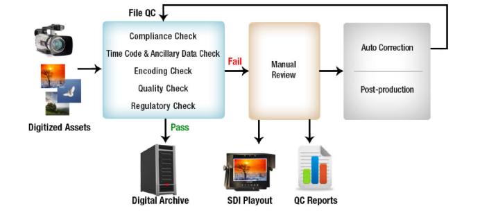
File-based
workflows are ubiquitous in the broadcast world today. The file-based
flow has brought enormous efficiencies and made adoption of emerging
technologies like Adaptive Bit-Rate (ABR), 4K, UHD, and beyond possible.
Multiple delivery formats are now possible because of file-based
workflows and its integration with traditional IT infrastructure.
However, the adoption of file-based flows comes with its own set of
challenges. The first one being – does my file have the right media, in
the right format and without artifacts? Fortunately, the leading auto QC
tools have kept pace with the growing technology advances to provide us
with this peace of mind. However, there are still many unsolved video
artifact issues that the auto QC tools grapple with. Video dropout, for
instance, is still a subject of research and significant advances are
expected over the next few years to more accurately detect these issues.
Once we know the issues, a natural question is – if the auto QC tool
can detect the problem, can it also fix it? The answer to this is not so
straightforward. In the analog and tape world, the content was as good
as it was created. Correction was limited to simpler processes like
signal level clipping, or color phase correction, which could all be
done at the delivery stage. Of course if the content deteriorated due
to tape issues like tears, twists etc., one went through expensive film
restoration techniques, if one could afford them – these were manually
assisted processes done under the fine eye of the editor. Can
auto-correction take care of these?
It so turns out that correction is not that simple in the file-based
world. The content is often stored and delivered in a compressed format.
It is also wrapped in containers to keep the audio, video, sub-titles
and a host of metadata information for the tools to work properly in the
workflow. In the file-based workflow, correction of the content
requires not only changes to the baseband content, but also re-encoding
and re-wrapping of the corrected content back to the compressed format.
We see the following challenges to the auto correction process:
Firstly, there are several baseband issues that are not even
detected automatically (in other words, they are outside the scope of
auto QC), forget about auto correcting them. Remember, analog world
people used manually assisted processes under editorial supervision.
Secondly, after the corrections are applied, through manual or
automated process, if the transcode including the re-wrap processes are
not managed properly, auto correction will introduce new set of issues –
the corrected content may even be worse than what you started with,
resulting in an unproductive looping.
How then can you depend upon an auto QC tool to do
auto-correction? Well, there are some issues that are amenable to
auto-correction, albeit a few. Most of the issues can be categorized in
three types: metadata inconsistency, video essence issues, and audio
essence issues. Whenever re-encoding and re-wrapping of content is
required to be done after correction, auto-correction via auto QC tool
may not work very well. On the other hand, metadata inconsistencies and
audio essence issues are more amenable to auto-correction. However,
correction of video essence issues typically do not converge when
performed on encoded files. In fact some of the video issues take place
due to encoding / transcoding process as well. The right workflow,
tools and techniques are needed to be deployed to make the
auto-correction flow work well for you.
It is a misconception that auto-QC tools can also auto-correct all
kinds of content issues. That is a sweeping generalization, and QC tools
should not fuel that false notion.
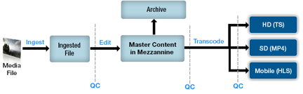
Figure 1 below, provides a typical high level file-based workflow.
After ingest, content is edited to create a mezzanine file which is of
high quality but with minimal compression. Different facilities can
select their own mezzanine format ranging from Motion JPEG to ProRES to
AVC Intra. Mezzanine content is then transcoded to multiple compressed
formats for different delivery formats.
Fig. 1 – Typical File-based Workflow
Since content undergoes some form of complex transformation at each
stage, this can potentially introduce stage specific issues within the
content. Each stage can introduce different types of issues. Similarly,
different levels of correction are possible at different stages.
Auto-correction works well if it is done on uncompressed digital
content, as it can be modified and corrected, before being compressed
and wrapped, much like the correction in the analog world. However, if
the content is already encoded and wrapped (e.g., transcoded content),
then auto-correction gets far more complicated – the re-encode process
after the auto-correction introduces other issues, making the correction
process divergent, less effective and even infeasible.
The ingest process often introduces artifacts like dropouts, signal
level errors in video and transient noise, wow and flutter in audio.
Auto-correction can work well at this stage if the digitized
uncompressed and un-wrapped content is available. Issues like video
signal levels, RGB color gamut, audio loudness etc., can be corrected in
the uncompressed digital content, which is then encoded and wrapped
into the mezzanine format like AVC intra and J2K. However, there are a
host of baseband video and audio issues which should not be
auto-corrected as one runs the risk of modifying the content.
The ingest process often introduces artifacts like dropouts, signal
level errors in video and transient noise, wow and flutter in audio.
Issues like video signal levels, RGB color gamut, audio loudness etc.,
can be corrected in the uncompressed digital content, which is then
encoded and wrapped into the mezzanine format like AVC intra and J2K.
Although, auto correction will work properly for most of the error
scenarios, however, the correction may modify the content to an
unacceptable level. For example, while correcting VSL or RGB color gamut
errors, the characteristics such as hue, saturation or contrast might
be changed affecting the perceptual experience of the viewer. Similar
example holds true for correction of transient noise in case of audio.
In these cases, manual inspection is also required after correction of
the content.
The similar argument holds for the editing stage. However, there are
several other types of issues that can crop up at the editing stage
which cannot be auto-corrected. Trying to merge two different media
during the editing process can lead to field order issues. We often see
customers complaining about VSL, RGB errors which get introduced at the
editing stage while adding special effects and graphics/text in the
content.
After transcoding, auto-correction can be done to a very limited
extent. Transcoding for delivery purposes is a complex transformation
where content is converted from one format to other. Many issues such as
audio / video corruption, blockiness, blurriness, pixelation, audio /
video dropouts, motion jerks, audio clipping etc. have been found to
occur during the conversion process, not to forget non-compliance with
audio/video formats or delivery specifications. Transcoders can also get
affected by buffering issues during transcoding process, leading to
overflow/underflow like situations. This can lead to introduction of
freeze or silence frames within the content. Even if we were to
auto-correct the issues, re-encoding the corrected content has the
potential of introducing similar issues in different forms and different
parts of the content. It is the best that auto-QC and transcoding tools
collaborate to correct these issues.
With this background, let’s now have a look at different kinds of
issues that an auto QC solution can detect in an encoded content and
what needs to be done to correct those issues.
Any QC solution will typically detect four kinds of issues:
Conformance Errors: These errors are primarily
non-compliance to different audio video standards. For example, an
MPEG-2 video stream must be compliant with the MPEG-2 video standard.
Any non-conformance needs to get reported. This category also includes
checking compliance of the content against different regional/delivery
specifications like DPP, IMF, AS-02 etc. Correction of these kinds of
issues generally requires the files to be re-encoded and re-wrapped.
Baseband correction is not required for these kinds of errors.
Metadata Errors: Each workflow and each stage in
the workflow has its own requirement in terms of metadata. For example,
an HD delivery requires resolution to be 1920 x1080. Content meant for
broadcasting in the USA needs to have a frame rate of 29.97 fps. Each
delivery or stage can have further restrictions on parameters like
scanning type, GOP structure, profile and level of encoded media, the
number of audio / video tracks etc. Any deviation from the acceptable
values will lead to content being rejected. So a QC solution is expected
to check for such metadata properties at different stages of the
workflow. Moreover, certain information like resolution, time-codes and
field order are present / encoded at both the wrapper and at the
audio/video level. If there is any inconsistency between the layers, a
QC solution should be able to report the same. If the issue is with the
wrapper layer (MXF, QuickTime, Transport) then only re-wrapping needs to
be done to correct the content. But in cases, where metadata
information at video/audio level is incorrect, one will need to perform
basic re-encoding along with re-wrapping. Example for such a case would
be if the US media environment requires content with 29.97 fps but
underlying media has frame rate of 24 fps. Simple fix for this issue
would be to introduce cadence pattern of 3:2 at video layer. Such
correction will need basic modifications to video layer and further
re-wrapping of compressed media.
Baseband Errors: These errors are different audio /
video artifacts which lead to deterioration in perceivable quality of
content. These errors are introduced because of stage specific
transformations as discussed earlier. This includes errors like freeze
frames, blockiness, dropouts in video and issues like silence, different
kinds of noises in audio. Correction of such artifacts first needs to
be done at the baseband level followed by the re-encode and re-wrap
processes.
Regulatory Compliance Errors: Different regions of
the world have their own regulations in terms of content quality. It
includes loudness control regulation all over the world. We have CALM
Act in the USA, EBU R128 standard is widely followed in Europe.
Likewise, the UK broadcasting market requires content to be checked for
any possible flash patterns to avoid photo sensitive epilepsy
situations. It is possible to correct these kinds of errors via baseband
correction followed by transcoding process.
Many kinds of errors discussed above will require compressed
content to be processed (re-encoded or re-wrapped or both) to remove the
errors. This processing is not as straightforward as it looks. It is
critical to decide where in the workflow, and with what tools these
errors should be corrected. Let’s take the case of an auto QC tool also
claiming to provide “good” correction capabilities.
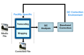
The tool comes with its own encoder. The workflow would look like this:
So a typical flow for auto QC and correction flow will work somewhat as below:
Mezzanine file is converted to delivery format using facility specific transcoder
The transcoded content is then checked using a QC tool and an output
report is generated; The report will contain detected errors, if any
If the content has no errors, it goes to the play-out stage
otherwise it moves to correction workflow which is an extension of the
QC tool here
The QC tool then performs correction on the basis of the reported
errors – it uses baseband correction algorithms along with its
transcoder for correction of the content
The corrected content is then ready and can be moved to the
play-out stage for final delivery. Up to this point everything looks
good and quite rosy. But users of this type of workflows may be in for a
shock when corrected content fails to meet the delivery requirements
and gets rejected. The situation is quite common because the corrected
content may not be of desired quality and may have additional new issues
which were not there in the first place. Let’s now look at the
challenges involved in the above correction process.
Transcoding
Transcoding is a complex transformation process involving conversion
of content from one form to another. A transcoder output is controlled
based on a host of input settings to handle varying flavors of container
and media formats, and to meet various kinds of delivery
specifications, in order to get the media with a required level of
quality and so on. The input settings control various internal processes
of the transcoder which includes motion estimation techniques, bit
budgeting, rate distortion model, selection of QP values and matrices,
the block interpolation/estimation processes, reference frame selection
and more. The final output of the content is dependent on the quality of
the said processes being used inside the transcoder as well as the
input parameters selected. Inappropriate selection and usage of input
settings to transcoder may result in output content not meeting the
intended requirements. A wrongly selected bitrate parameter can degrade
the quality of the output content with new artifacts (out of RGB color
gamut errors, video signal level errors, blockiness, softness etc.).
Another such scenario can come up while selecting display field order
for the output content. An SD DV content (bottom-field first by default)
when transcoded to MPEG-2 video (top-field first by default) will lead
to motion-judder issues in the output because it was required to change
the default field order input value to the required one. Thus in order
to create good quality and optimally compressed content, several
parameters need to be fine-tuned and managed as per the facility’s
requirement. Setting these parameters/options even for the best
transcoder requires expertise. One cannot expect another ‘generic’
transcoder to be able to perform at the same level. It is hence to be
expected that any attempt to re-encode the content with another encoder
could lead to negative effects. The second encoder, while trying to
encode the corrected content at the same bitrate may follow a different
bit allocation strategy leading to compression issues like blockiness
etc. It is also highly possible that a new encode process can completely
miss certain information that is vital for the content. To name a few,
user data present at video level may get lost in the process of
transcoding. Another example would be watermarks, where the generator
leaves a special mark in the video/audio to establish publisher
information. It is impossible to replicate or reinsert these watermarks
unless the same set of tools is used during correction. It is also quite
possible that some of the settings are not even consistent among the
two transcoders. For example, the other transcoder might be using
different motion estimation techniques or rate distortion algorithm
inside it or it may also happen that the original set of tools inside a
profile or level is not supported. That will cause the correction
process to generate media data with unacceptable profile / level and
content quality, which will be rejected later at the play-out stage. At a
minimum, one should use the same encode process and tools as used
during content creation.
However, issues don’t end here. Even if we plan to use the same
transcoder, it can potentially introduce new errors while correcting
existing ones.
The re-encoding process leads to loss of some audio / video
information which in turn impacts the quality of content. Degradation in
quality, though minimal for most of the cases, will depend on the
encoding parameters and the content itself. If re-encoding is done to
reduce bitrate of the content, it will lead to compression artifacts
like blockiness, pixelation etc.
Conformance errors may also get introduced because of faults in encoder under certain conditions.
In a few cases, it is also possible that metadata errors may be
introduced, if the wrapper information is not set correctly; one such
example could be the field order – assume a case where the field order
has changed after re-encoding but the same is not reflected at the
wrapper level. Such inconsistencies can arise and thus there is a need
for a better management of such issues.
Re-Wrap
Another big challenge in a correction flow is to re-assemble /
re-wrap the corrected and compressed media with exactly the same
properties as the original file. Transcoders come with their own
built-in Muxers or can be integrated with third party Muxers to wrap
compressed media into a container. The media workflows in the broadcast
industry use their own set of unique tools to transform and assemble
media information. A different re-wrap tool or the same tool with
differently encoded essence will produce different results. This
implies that the corrected output file may be different in properties in
comparison to the input source file. An example is MXF version, where
the original file may have been assembled using a lower version. But if a
new Muxer used during the correction process uses a higher MXF version,
it may cause interoperability issues in the workflow. Also, the MXF
specification allows addition of new proprietary ULs that can be
generated and interpreted by specific Muxers / applications. For other
tools, it acts as ‘Dark Metadata’ that will be ignored while processing.
Hence, the second Muxer for such cases will ignore the dark metadata
and the proprietary information would be missed in the corrected
content. Hence, it’s an imperative to avoid the usage of two different
Muxers in your correction workflow.
Baseband Correction
In baseband correction, there are issues like video signal level, RGB
gamut, field order, digital dropout, loudness related errors which can
be intelligently corrected. For such issues, the content is first
decoded. Algorithms are then applied on the baseband / uncompressed
signal to intelligently correct them for the reported issues. Once the
baseband correction is done, the content is re-encoded and re-wrapped.
Can we fully rely on baseband correction? Perhaps not. It is possible
that a certain correction may introduce fresh errors during re-encoding
process. For example, VSL / RGB correction may end up altering the block
boundary pixels which in turn leads to blockiness like issues in the
corrected content. There are additional set of errors which cannot be
auto corrected like: freeze frames, silence and certain noises. If the
capture device, for some unknown reasons, fails to capture a few frames,
it can potentially lead to a freeze like situation. It’s not possible
to re-create those dropped frames during correction cycle until we have
access to the dropped frames. It is also possible that certain special
effects that are added to video may cause QC solution to detect those
effects as blurred or pixilated area in the video frame. In this
scenario, it is not desired to correct the content. Hence, there is a
need for manual intervention to understand these anomalies and then take
appropriate corrective measures. Some of these aberrations maybe
intentionally be introduced as special effects, and therefore, needs no
correction.
Proposed Workflow
Auto correction has its own set of challenges as mentioned in the
previous section. Because of these challenges, it is not practical to
expect an auto-correction tool to be a panacea for all issues. In fact,
there is a class of issues that can be auto-corrected. Coupled with the
right set of tools and workflow, one can make auto-correction work under
these limited circumstances, such as:
Legalization of audio and video content and some cases of regulatory compliances.
These include audio loudness, true peak, loudness range, audio levels,
audio noises like background noise, crackle. On the video side, it
includes video signal levels, RGB color gamut, cases of video dropouts
and also flashiness patterns. The proposal here is to limit the role of QC solution to baseband correction.
The correction flow can then rely on facility specific transcoder for
its encoding needs. For example, a facility may depend on Dolby tools
for encoding of AC-3 /Dolby-E content. In such a scenario, the role of
auto QC tool is to perform baseband correction for audio and then submit
the encoding job to Dolby tools. This would ensure consistency between
the original content and the corrected content in terms of metadata and
quality.
Another practical use case here would be integration of auto QC
tools with the workflow automation / transcoding solutions like
Telestream Vantage. Once the content is transcoded, QC tools can
then perform content analysis followed by intelligent correction
depending on the detected and correctable errors. The workflows can be
further configured to feed the corrected but uncompressed output from QC
tools to in house transcoders like Vantage for re-wrapping/re-encoding.
Submission of transcoding jobs to the transcoder after correction can
be initiated in multiple ways. In some cases it can be as simple as
dropping a file in a Watch Folder while for other cases, a QC solution
may need to invoke transcoder’s web services to start the required job.
For larger workflows, it would also make sense for MAM /workflow
automation solutions to create some kind of correction / self-healing
workflows so that transcoding action can be invoked once correction
process is done. These discussed approaches would require the QC
solution to be integrated with some of the widely used transcoders /
workflow solutions so that a large number of customers get the benefit.
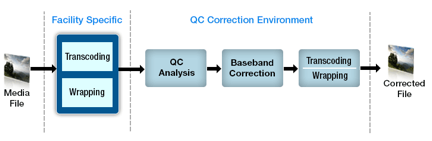
Such a flow would typically look like this.
Fig. 3 – Proposed Transcode & Correction Workflow
The steps followed in the proposed flow are listed below:
Media file is analyzed using the QC tool
The content moves to the play-out folder if it passes. In case of a
failure, the content is de-muxed, decoded and then corrected for
anomalies at the baseband layer, if required
Content is then submitted for transcoding using facility specific tools
The correction process may also need to specify new parameters / settings to be used during the transcoding stage
Modes for submission of transcoding job can vary as discussed earlier
The use of the same transcoder will eliminate lots of potential
issues and make the above flow more practical and amenable to
correction.
Most of the challenges in correction process arise because of
re-encoding / re-wrapping. Correction which does not change the size of
the compressed content can be handled without a possible re-wrap. That
is true for uncompressed content based on baseband correction. Audio
content in a lot of cases is stored in an uncompressed manner using
formats like PCM, AIFF, BWF or AES3, owing to the fact that audio
requires much less data size as compared to video. Since uncompressed
content occupies fixed block sizes at certain offsets, it is not
necessary to re-wrap the whole media. A smart correction tool can simply
perform what we call as in-place correction. The goal here is to
un-wrap the audio, record the length of each uncompressed audio block
with the corresponding file offsets. Once baseband correction has
happened, corrected content can then be written back to the main file
block by block using the recorded information. This way wrapper
information or media data from other tracks remain untouched.
The above strategy is really useful for correcting audio errors like
program loudness, loudness range, true peak etc. and it works
efficiently in an iterative correction process. Errors like loudness,
loudness range cannot be corrected in a single run. They may require
multiple correction runs to reach desired levels. In-place correction
ensures that no temporary file or buffer needs to be maintained for
storing intermediate media. Corrected output values can be re-written to
the final file for each iteration. This strategy works out not only to
be efficient but also fast. The concept of in-place correction can also
be extended to uncompressed video formats like YUV, RGB. But since
uncompressed video formats are not widely used, it may not be very
beneficial to the end customer.
Another class of issues that can be corrected is metadata inconsistency errors.
In cases where the encoded content is correct, but container metadata
has been wrongly encoded, the problem of correcting the content requires
only metadata changes for specific fields. These corrections can be
applied without the need for transcoding or rewrap of the content and
are very amenable to auto-correction. This again falls into the category
of in-place correction. For -example, if there is a discrepancy between
the resolution information present at the MXF layer compared to the
actual video resolution, the resolution information at the MXF layer
needs to be corrected by directly accessing the headers and there is no
need to transcode or re-wrap the file. This scenario would include
correction of metadata fields like frame rate, chroma format, aspect
ratios, sampling frequency, encoded duration etc.
To conclude, auto QC is now an essential component in file based
workflows and is widely used these days. This has triggered the need for
a QC solution which can auto-correct errors in order to save time and
resources. It is based on the thought that if a tool can detect error,
it can also potentially fix it. But auto-correction in the file-based
world is a more complex process and should not be trivialized. A QC tool
having in-built support for auto correction including transcoding has
issues of its own. Transcoding and re-wrapping processes if not managed
properly, can introduce fresh issues into corrected content leading to
further degradation of content quality. Hence, it is not possible to
fully rely on such auto correction flows. A more practical approach
would be to reuse facility specific tools for encoding needs during the
correction process. In such scenarios, the role of a QC tool is limited
to baseband and metadata correction or setting the transcoder correctly.
A smarter in-place correction strategy can also be adopted in case of
uncompressed content. Having said this, there is still a set of issues
which requires manual intervention and thus cannot be auto corrected.
Hence, the scope of QC tools for auto correction is limited but feasible
for a set of issues provided we use the right tools, workflows and
techniques.
The advanced auto QC tools can be used to automatically detect the video and audio artifacts, focusing on legitimate auto-correction in a controlled and restricted manner.
The
buzz about 4K is at full volume now – how to record it; how to edit and
package it; how to display it. And there is another consideration: how
to test it for quality. Even though there is no widespread distribution
of 4K content yet, that day is rapidly approaching, and broadcasters and
equipment manufacturers alike have to be ready with equipment and
workflows that will yield the most reliable, pristine signals and the
best possible 4K viewing experience and also in every format on every
screen. Not only do these factors affect viewer satisfaction and loyalty
and, in some cases, subscriptions; they also affect ad revenue, service
level agreements, and compliance. So, testing and verifying quality is
no small thing for a content distributor.
The industry trend is toward more programming and more devices with
varying screen sizes. At the same time, new and more efficient encoding
standards will allow for additional channels over the same or smaller
data rates. These trends make for a seemingly infinite number of formats
to manage, making it all the more critical to put the right equipment
and workflows in place now.
Broadcasters and service providers who are planning to launch 4K
services are in the process of determining their ideal distribution
scenarios right now, using real-world analysis and QC tools to research
the technology requirements of delivering 4K content to a wide range of
services: real-time TV channels delivered through cable IPTV or
satellite, file-based delivery of VOD content, and streaming content
over the Internet. Based on that research, they will define their
workflows and assemble the right combination of gear to meet the rapidly
approaching demand for 4K content.
And when those theoretical exercises become reality, and the content
distributors must put their carefully planned 4K workflows into
practice, they’ll use those same tools to conduct testing and QC after
the content goes live. A typical content distributor could receive a
program feed from a number of sources, such as a satellite, an existing
network, or an uncompressed file from a postproduction process. From
there the operation provides both high-bit-rate encoded video for
broadcast and at the same time puts out compressed “adaptive streams” as
a number of profiles, in different bit rates to support any number of
OTT platforms. As time goes by, more and more of those uncompressed
source streams will originate from 4K content — content that must be
decoded on the fly, recorded, ingested for QC testing, and encoded using
the compression codecs required by the target devices. During the
testing phase, the system must provide an automated means of testing key
attributes of video quality, audio quality, lip sync, and loudness.
What sort of solution can handle testing for 4K video delivery both
now, in the research phase, and after the content goes live? What goes
into the ideal testing tools?
Must-Have Items for Testing 4K Video Quality
Most important is the ability to ingest, record in 4K resolution, and
test content from any compressed or uncompressed video source using
today’s SDI-type interfaces, whether the signal comes from an IP
network, a file, or an uncompressed feed from a video infrastructure.
This also includes files from the editing suite, such as multiple frames
of uncompressed sequences of any length, or lightly compressed
mezzanine-level files.
The testing tools should also be able to decode any encoded file in
the current MPEG or JPEG standards, as well as in emerging encoding
standards such as HEVC. In addition, it is critical that the system be
able to play back the content in every resolution required for delivery
to every screen, from UHDTV and HDTV to resolutions for mobile devices.
Another important characteristic is a flexible input/output
architecture that lets users test individual devices and then place them
into a test network structure — either at a live broadcasting plant, a
content delivery network, or in the lab of the product’s manufacturer or
developer.
The ideal test solution should also support not only 4K, but the full
range of resolution levels, from streaming formats for handheld devices
and PCs; to today’s most active broadcast-level HD formats; to
high-frame-rate HD.
The Importance of Audio Measurements
A 4K testing tool should include audio, because audio requires
several tests in addition to video. In order to account for all audio
variables, the testing tools must perform three key audio measurements.
The first, perceptual quality testing, simulates a human perception test
and creates a measurement that is as close as possible to an actual
subjective study done in a standardized environment.
The second critical audio measurement is for performance, which
identifies performance issues with audio devices or audio in the network
chain. These tests find audio faults such as silences and glitches, and
a sufficient solution should log the failures for instantaneous review.
Audio performance testing also should cover lip sync measurements with
millisecond accuracy.
Audio loudness testing, which has become extremely important with the
adoption of global loudness standards, is the third audio measurement
that the ideal test solution should include. Effective loudness testing
involves applying loudness standards to every distributed program’s
audio channel groupings and reporting a measurement.
When searching for a way to analyze 4K video quality, it’s important to pay attention to those characteristics. The right test solution can mean the difference between success and failure in the world of 4K content delivery.
Over the years, content creators and broadcasters have accumulated large libraries of assets in analog formats. With the switch to the digital workflow, there is a critical need to digitize all these assets because of multiple reasons:
Risk of losing the asset forever if not digitized
Preservation of asset for posterity, since digital format offers immunity from degradation over time
Getting the asset ready to be used and monetized in today’s digital workflows
Space and operational costs optimization
As a result, the digitization of analog tapes and archiving into digital libraries is critical to complete the transition to the file-based digital world. Post digitization, the content becomes the master – the analog tapes are thrown away. The asset, however, is only as good as the digitization process. What if the process was faulty, or there were errors introduced during the digitization process itself – the tape head was not aligned, the tape was read twisted, there was audio and video drift, or some audio track went completely missing, color bleeding happened, or maybe there was too much hue or red in the ingested material, or the tape head was not clean and it inserted a vertical line on all the frames – the possibilities of things going wrong are immense. And all of these are known to happen. If the process is faulty in anyway, the loss is immense – priceless assets will be lost forever. So what does the archiving process rely on – eyeball QC of the ingested content. But with thousands of hours of content to be digitized, manual QC is neither a practical nor a good option. The manual process is unreliable and is fraught with errors. It lacks consistency and with human fatigue setting in, it tends to be unreliable. Further, there are several errors that are not human detectable, but only machine detectable in the file-based digital workflows. Additionally, metadata checking can be erroneous – the asset with wrong metadata may also be practically lost in the archives, never to be retrieved when needed.
To overcome all the shortcomings, auto QC is now an essential and central part of the digitization workflow. The process is fast and efficient, consistent and reliable. When coupled with a manual review process on random and/or erroneous digitized content, the results are vastly improved in terms of the digitized content quality. Good auto QC tools with deep video quality checks for analog dropouts are increasingly deployed in the tape archiving process. Auto QC quality checks need to be enhanced to handle many digitization specific issues. Sensitive and detailed video dropout checks are critical for good archiving and one cannot take shortcuts with simple file-checking tools – industry grade QC tools with in-depth video dropout checks specially developed for analog tape ingest need to be deployed. A word of caution – the field of video dropouts is a subject of R&D with several checks still being evolved. This paper explores some of the checks in depth and how auto QC is being deployed in the digitization workflows.
The Need for Digitization and the Process
Most archives, broadcasters, universities, governments and television stations have thousands of hours of content accumulated and stored in analog tapes over the years. A typical broadcaster may have nearly 100,000 to 200,000 tapes of one hour duration collected over a ten-year period. While a few stations might have Super 8 or U-Matic tapes, majority of the tapes are a mix of Betacam (SP/SX Digital/IMX), XDCAM or HDCAM.
Preservation of the tapes requires not only space, maintaining correct tags, sorting of the tapes in correct sequence (like all sequence of sports together), the mere number of tapes creates a huge problem for the management to effectively use the tapes when needed. Also, the quality of the tapes deteriorates with time due to the inherent nature of magnetic tapes. In many cases the recoverability of the programs from the old tapes can no longer be guaranteed. Maintaining the tapes is a costly affair while the quality of the content is still not guaranteed. The digital workflow offers a solution to this.
Once tapes are digitized, facilities can achieve multiple benefits from the same. These include:
Preservation of assets without the fear of quality loss or degradation
Optimization of space and operational costs – retaining large archives of tapes in temperature and humidity controlled spaces is expensive while storing digital content in files is a lot less expensive
Faster access and retrieval from the archives with enhanced metadata search capabilities
Online content for new audiences and monetization possibilities
Facilities are fast migrating to complete digital and file-based workflows and getting rid of the old tape archives.
Figure 1 below provides a typical digitization process deployed during migration.
Stage 1. Tape Preview
At this stage, the different type of tapes (IMX, Betacam, HDCAM, XDCAM etc.) are sorted and tagged. Tapes are also physically checked for tape quality, presence of any foreign body in the tape, physical damage, tape twisting etc. If some of the important tapes are found to be damaged considerably, the tapes are usually sent to external specialist for restoration.
Stage 2. Tape Preparation and Cleaning
The tapes identified and sorted for digitization are moved to the ingest area at least 24hours before the actual ingestion of the tapes to avoid sudden expansion/contraction of the tapes. The ready tapes are then loaded in a tape cleaning machines to remove the dust and residuals like oxide deposits. With a huge number of tapes to be digitized, barcode labels are generally put on the tapes for better tracking and mapping of the metadata to the assets. Barcodes are also used by the downstream tools to automatically select the transcode profile during the digitization process.
Stage 3. Digitization of Tapes
At this stage, the tapes are played back and the ingested digitized content is encoded to house formats like Jpeg2000, AVC Intra etc. For large scale digitization, automated robots are deployed which can feed the tapes to VTR automatically from the stacked tapes using barcodes. Apart from creating the digitized files, a database containing the metadata is also updated for the digitized assets. A low-res proxy file is also generated along with the hi-res files.
Stage 4. Quality Checking
The quality of the ingested content must be checked to ensure proper ingestion. Post digitization, the digital content becomes the master and the tape becomes redundant. It is therefore essential to ensure that the right quality has been achieved in the digital master, before the tape is thrown away. If the content volume is low, one may rely on eyeball or manual QC to check the digitized content quality. However, with hundreds of hours of digitized content, manual QC is not a practical option. The manual process is also fraught with errors:
Manual QC lacks consistency
Some errors are not perceptible, but manifest themselves only during playback on some equipment
Human fatigues sets in, leading to unreliable QC process
Metadata checking can be erroneous – the asset with wrong metadata may also be practically lost in the archives, never to be retrieved when needed
Large scale digitization hence relies on auto QC tools to assist in the quality checking process. However, as we will see in the next section, there are a host of issues that can crop up in the storage of tapes and the playback process, which impact the video quality of the digitized assets. Similar issues can arise in the audio as well.
All these can lead to various different kinds of artefacts in the ingested digitized content. These artefacts are classified as “analog dropouts” in the video and the associated audio. A good auto QC tool should be able to reliably and accurately detect such artefacts. While one can identify these artefacts with visual inspection, identifying all such issues automatically through auto QC tools is still a subject of research and a lot of R&D is being done on the same (we will go into more details on this in the next section). Some of the advance auto QC tools provide a higher degree of reliability, accuracy and coverage of these analog artefacts, and are much better suited for deployment in the digitization workflow.
The auto QC process can be complemented with a manual review process to finally accept or reject the digitized content.
Stage 5. The Archiving Process
Once the digitized content is accepted, it is then archived using the selected archiving software. Metadata is updated, along with the proxy file. The process is complete and the corresponding tape can be discarded.
The Auto QC Process
As discussed above, auto QC is now an essential and central part of the archiving workflow. The auto QC process is fast, efficient, consistent and reliable. When coupled with a manual review process on random and/or erroneous digitized content, we achieve higher levels of productivity with vastly improved results.
Figure 2, below, shows a typical auto QC workflow in a digitization project.
There are mostly four types of checks that are done as part of a quality checking process on digitized files:
Checking the compliance of the generated content
Checking for timecodes and metadata
Checking the baseband quality in audio and video
Checking for encoding/transcoding errors, if content is compressed
Compliance and metadata checking is a straightforward process needed to ensure that digitized content will work with all downstream tools. It is similar in nature to the checking done in current file-based workflows. The real complexity comes with ensuring that baseband quality of the digitized content is above the defined and agreed to threshold level. This becomes even more challenging when the same has to be done reliably with auto QC tools. Video issues can manifest themselves in different ways, and each one of them requires deep R&D to detect them reliably and accurately. With one large broadcaster, we saw over 50 different types of video quality issues in the digitized tapes. In the next section, we describe some of these in more details.
Quality Issues and Detection
The information embedded within tapes is in the form of voltage signals. The formation of each pixel, frame or picture is attributed by stored signal values on magnetic tapes. Alteration in natural variations in these signal values will lead to incorrect color values for captured pixels and cause errors in formation of fields, frames or pictures. These alterations are caused due to mishandling, ageing and improper maintenance of tapes. These can also be due to errors within the digitization process being used. The resulting video artefacts in this way are collectively termed here as analog dropouts. Some examples are blotches, scratches, miss-tracking, head clog, skew error, horizontal/vertical sync pulse loss, etc. The following sections will discuss some of the commonly observed analog video dropouts in further detail.
Horizontal / Vertical Sync Pulse Loss
A video frame consists of multiple horizontal scan lines spread across the vertical resolution. A specific voltage level exists at the end of each scan line indicating its end and start of the next scan line. Any variation in the voltage level (due to noise) will shift content lines, perceptually viewed as horizontal lines. This is shown in the snapshot below (Figure 3 a).
Vertical sync pulse is another such voltage level controlling the start/end of a new video frame. Any deviation in the voltage level will disturb the start of the formation of the next frame. Vertical sync pulse loss merges the two adjoining frames at the frame boundary (Figure 3b).
Skew Error
A magnetic tape can have dimensional changes due to continuous expansion or shrinkage of the tape surface over time. Due to this, the recorded tracks are affected by changes in length and angle resulting in misalignment with respect to the playback head. During playback/recording, this loss in alignment will shift a band of scan lines at the top/bottom of the picture. This horizontal shifted portion of the video frame at the top or the bottom part is termed as Skew Error (Figure 4).
Line Repetition Error
An analog to digital conversion device gets the video data in the form of scan lines. The buffers that store each scan line data are updated regularly after each sample and hold duration. The line repetition error is caused due to issues in controlling the signals – the current scan line is not captured and is replaced by the previously fetched scan line. This error in the control signal continues for a while and the same is manifested as a repeated set of horizontal content lines. The artefact is shown in Figure 5.
Blotches
Blotches occur due to presence of dirt/sparkle on the surface of a magnetic tape. Dirt/blotches disrupt the reception of signals during video data capture. The area for which the data is not received, appears as white or black spots. Snapshot of the video frame with blotches is shown in Figure 6.
Scratches
Scratches appear in the video frame due to removal of oxide on the tape surface. The loss of oxide is due to wear and tear after prolonged or continuous usage of a tape. Generally, these scratches are in the form of thick horizontal line with some break at the boundary. The artefact is shown in Figure 7 below.
Chroma Phase Error
Composite video signals consist of chrominance components combined with luminance component using the phase modulation method. Any deviation in the phase will affect all the constituent components. With the phase error, the hue and saturation for the pixel colors may change and this will result into deviation of the colors from its natural values e.g., skin color, natural color of leaves or flowers sky etc. One of such examples is shown in Figure 8.
Dot Crawl / Rainbow Artefact
While capturing from a tape using composite signals, sometimes luma can be misinterpreted as chroma or vice versa. If chroma is treated as luma, the resulting artefact is termed as Dot Crawl. On the other hand, if luma is treated as chroma, the resulting artefact is termed as Rainbow Artefact.
Ghosting
The ghosting artefact is perception of weak shadows around the edges of the primary visible objects within a scene. It happens due to transfer of magnetic signals across the adjacent tapes. A snapshot frame for this error is shown in Figure 9.
Apart from the above listed set of errors, other errors may also get introduced while capturing color values corresponding to each of the pixel location in a frame. In some cases, values are not retrieved at all; localized patches are created abruptly within the content. If the captured values are different from its natural value, video signal level and out-of-gamut errors are introduced in the captured video sequence. Apart from these errors, different kinds of noise or noise patterns can be perceived due to noise introduced while capturing analog signals.
Fortunately, there are processes and tools to correct not all but some of the errors introduced after analog to digital conversion. These tools or processes consider specialized steps to correct the tape device or the conversion process itself. There are post-processing tools as well to remove any noise in the digitized content, to correct the hue / saturation / balance / contrast of colors etc. But before applying any such correction step, it is required to know if there is an error and what type of error it is. The knowledge about the type of errors will help in selection of the correction steps to be followed.
Similar to videos, audio samples too are stored as voltage signals on magnetic tapes. Any aberration while capturing the audio signal during the digitization process can lead to audio distortion of different types as discussed below.
Audio Click/Audio Crackle/Transient Noise
Click/Crackle/Transient Noise/ Glitches are introduced due to scratches and dust on the surface of a tape. These are localized degradation that only affect certain groups of samples and thus cause a discontinuity in the waveform.
Scratches lead to disrupted audio samples during of the digitization process. These are perceived as ticking/popping/scratchy kind of noise lasting for a very small duration.
Audio Dropout
Audio Dropout is defined as distortion in audio signals in which silent frames of small duration (from 4ms to 300ms) are introduced in midst of normal audio data. It is characterized by abrupt fall in the signal level at the event of audio drop and abrupt rise at the end of audio drop frame.
Audio Dropouts are mostly introduced during digitization due to damage appearing on the tape. If a certain part of the tape is damaged, it won’t be possible for the head to read the corresponding audio data resulting in audio loss for that specific duration.
In addition to the above defects, the digitization process can also cause Audio Clipping. Because of dust and dirt contamination, it is possible that voltages become so high that it causes few of the audio samples to go above the legal range of 0 dB.
For detection of audio defects, checks like loudness checks, audio dropout, audio clipping, checking for different type of audio noises are very common during the quality checking process.
If closed caption and burnt-in subtitles are present in the content, advanced quality checking tool will not only check for their consistency and dropout, but it will also make sure they are present in safe area of the screen.
Unlike the errors in compressed digital data, the errors in analog medium are difficult to model. The analog data errors are random and do not follow a known pattern. This is also due to variations in the conversion processes or varieties of electro-mechanical components used inside tapes. Because of this uncertainty, detection of these artefacts is quite tedious. Highly specialized image and video processing concepts and algorithms are required for accurate and reliable detection of errors in the digitized data.
The Challenges Faced by Auto QC Tools
Selection of a correct auto QC tool for digitization is not only critical, but it has direct impact on the quality of the digitized content. A good auto QC tool can make the digitization process more efficient by detecting issues accurately and reliably. Algorithms to detect analog errors are more complex than that of digital errors. The detection algorithms need to consider and model various kind of non-linear processes followed during analog to digital conversion. Error detection algorithms have been developed for detecting some but research is continuing for the difficult ones where it is complex to model the actual error context. The auto QC tool you deploy in your workflow will provide benefits which are only as good as the depth and accuracy with which it detects such analog dropouts. Some QC tools just do a lip service in the name of detecting such issues, and it is advised that a proper tool be selected after due testing of the results. Fortunately, there are some industry grade QC tools, with in-depth video dropout detections available now. These tools have exhaustive checks dedicated to the analog tape ingest process and have been successfully deployed at large archiving projects.
The digitization of tapes and archiving to digital formats is a necessity to complete the transition to the file-based digital workflow. During this process, it is critical to use the right set of tools to ensure the quality of the content being archived. Artefacts can manifest in multiple ways in these tapes and need to be detected. Detection of these artefacts called analog dropouts is complex and several deep algorithms have been developed for the same. While a lot more research needs to be done to cover a larger set of analog dropouts, using the right auto QC tool during the archiving process helps detect these complex analog errors more accurately and reliably, and enables you to preserve and deliver high quality of the generated content.
Implementing a media management system is considered to be a risky business. Like national infrastructure programmes, the perceived complexity, upheaval and perception of failure can be so daunting that the risk may seem to outweigh the reward. But, like so many business technologies, MAM have been transformed in recent years with the advent of open standards and interfaces.
It’s time to debunk some common MAM myths.
Perception: MAM implementation projects cost millions
Truth: MAM software is available from as little as £10k
It’s not surprising that MAM projects are perceived as expensive – before its collapse the notorious BBC Digital Media Initiative had racked up a £96m bill and even comparatively ‘small’ projects at a large facility or national broadcaster in recent years have averaged a few million. For most operators those figures are unimaginable. But a pragmatic approach to scope and implementation can deliver real value at low cost. The principal enabler here is the cost of the MAM software.
Rather than starting at £1m as they did ten years ago the cost for modern product has dropped to around £150k for a base system – with some tools available for as little as £10k. Cloud or hybrid service models make it possible to pay-as-you-go for a fraction of the cost and without long term commitment.
For on-prem’ deployed systems the cost reduction is largely as a result of use of open, service based technology as well as vendors designing the foundation tools to be less specific to a given function or workflow. Modern MAMs are architected on the basis of a core which is functionally augmented with bolt-ons or plug-ins.
Perception : MAM’s rarely deliver value on investment
Truth : A targeted approach delivers immediate benefits
The return on an investment of millions will be long – often too long to make a strong business case, but now that MAM system implementations can be achieved for a fraction of the cost, it’s easier to prove real value in day-to-day operations and to the bottom-line.
With relatively inexpensive entry points, operators can focus on a specific difficulty in the operation and prove or refine an approach before tackling other areas in the workflow. Defining and building workflows is no longer time consuming so demonstrating operational benefit may be achieved in hours instead of months.
An important caveat here is scalability though – do ensure that the chosen MAM vendor can scale as you broaden deployment – a modern MAM should readily scale from a few, to a few hundred users without even taking the system off-line.
Perception : Implementation of a MAM system takes months – if not years
Truth : You can be up and running in minutes
MAM history is littered with projects that took years to implement and were obsolete by the time they were delivered. This was generally caused by an over-focus on up-front analysis driven by the need to understand the operating model ahead of configuration which itself was driven by the complex and time-consuming nature of configuration.
A modern MAM can be up and running in minutes – or seconds in the case of cloud-based system. From the ‘vanilla’ base an operator can quickly create users, set access permissions and build simple production workflows for transcode and delivery or review and approve. A modern MAM allows operators to build and test workflows as they go – an agile approach which delivers rapid results. Because it is now quick and easy to configure and implement a base system, and then customise the system to your needs, there is less pressure to perform a perfect up-front analysis, and more tolerance for changing requirements.
Some products such as the Blue Lucy Asset Manager (BLAM,) have built-in tools that deliver immediate benefits.For example; BLAM will index existing storage pools and create browse clips without moving the original media and while maintaining project hierarchy. This tool means that projects can automatically be brought under management of the MAM without any user intervention or interruption to operations.
Perception: Deploying a new MAM means replacing the systems we have.
Truth : An effective MAM will integrate with legacy and 3rd party systems.
Many MAM projects are initiated on the premise of replacing one or more existing systems. The narrative runs “… we can replace these three systems with this one new system. Operations will be simpler, delivery will be faster, and support will be easier……” This, all too common, one big new universal panacea system mantra rarely (never) actually delivers. Subsuming functionality, particularly in active systems is fraught with risk – risk which always translates to cost. The simplest and most cost effective approach is rarely replacement.
A modern MAM vendor should be able to provide connectors to commonly used 3rd party systems and be willing to build these for legacy components. These connectors are used to get essential data from 3rd party systems, process it and if necessary, put data back. The MAM should be capable of acting as the integration layer that connects systems and, importantly, provides a single view of the operation.
This is far less expensive and risky than incorporating functionality in a new system. It is also likely that specialist systems provide a better, or more specific, capability than one system trying to do everything. Do be wary of vendors who are reluctant to integrate with third parties or boast that their systems can absorb operational capability.
Perception: MAMs only manage media.
Truth : Modern MAMs provide broader capabilities including workflow orchestration and enterprise reporting.
Very few modern MAMs are just asset managers, but perversely the term MAM has stuck because it’s one that everyone understands. Rather than just being limited to a static repository where media objects are stored and made accessible, many MAMs include key operational functions such as automatic and task-driven workflows. The automation of tasks such as transcoding in a workflow obviously removes manual process but of equal benefit is a task driven workflow which drives operation procedure – i.e. the people.
More sophisticated systems (like BLAM) can provide data and intelligence on a broadcast / media operation, enabling workflows to be adjusted for maximum efficiency. Efficiency for a content producer translates to saving money in the production or distribution process or reaching wider audiences on an ever increasing number of consumer platforms.
Perception: MAM projects require big investments in infrastructure and storage
Truth: Modern MAM’s use the cloud for scalability
Although the cost of MAM software is largely flat (or at least should be,) the cost of storage is dependent on the volume of media being produced and stored. When planning on-prem’ deployments, system designers – understandably – plan for the worst case scenario, which means high storage costs and big CAPEX spend.
Using a combination of on-premise and cloud storage allows media operators to avoid spending money up-front for capacity that they may or may not need in the future. MAM vendors like Blue Lucy are able to seamlessly blend the on-prem’ and cloud-based services, providing access through a single user experience. This approach offers huge flexibility for ‘burst’ capacity and de-risks a strategy of cloud migration.
The most commonly cited advantage of deploying IP video networks in production and other operational applications is the ability to use commercial off-the-shelf (COTS) IT-based infrastructure, which takes advantage of the economies of scale of the IT industry when compared with the relatively small broadcast industry. Additional advantages of reduced cabling cost and weight along with the much greater routing flexibility that offers more flexible production options. These advantages have captured the industry by storm and broadcasters are already working on early deployments of IP video networks. Not far behind deployment is the need to efficiently diagnose and resolve faults.
IP introduces new technical and skills challenges. These include jitter, latency and the risk of dropped packets and network asymmetry that results in different path delays upstream and downstream.
Deploying IP for video production applications is effectively the collision of the two worlds of video and network engineering. Video engineers are comfortable with the use of SDI, coaxial cable, patch panels, black burst and tri-level sync for timing and above all, monitoring signal quality. The challenge for the video engineer is to understand IT technologies and impact of an IT infrastructure on the video.
On the other hand, network engineers are familiar and comfortable with, IP flows, protocols, network traffic, router configuration, Precision Time Protocol (PTP) and Network Time Protocol (NTP) for timing. The biggest difference however is that in most data center applications, lost data can be re-sent – this is not the case with high bitrate video. The challenge for the network engineer is in understanding video technology and its impact on IT infrastructure.
Overcoming jitter
In any digital system, jitter is any deviation from the regular periodicity of the signal. In IP networks jitter is the variation of the packet arrival interval at a receiver. If the network routers and switches are all configured and operating correctly, the most common cause of jitter is network congestion at router/switcher interfaces.
The application within a network element will likely require the data to be received in a non-bursty form and as a result, receiving devices adopt a de-jitter buffer, with the application receiving the packets from the output of this buffer rather than directly. As illustrated in Figure 1, packets flow out of the buffer at a regular rate, smoothing out the variations in the timing of the packets flowing into the buffer.
Figure 1. Packet jitter is deviation from the periodicity of the packet arrival interval.
The rate of packets flowing out of the de-jitter buffer is known as the “drain rate.” The rate at which the buffer receives data is known as the “fill rate.” If the buffer size is too small then if the drain rate exceeds the fill rate, then the buffer will eventually underflow, resulting in stalled packet flow. If the sink rate exceeds the drain rate, then eventually the buffer will overflow, resulting in packet loss. However, if the buffer size is too large, then the network element will introduce excessive latency.
Jitter can be measured by plotting the time-stamps of the packet inter-arrival times versus time as shown in Figure 2.
Figure 2. Packet inter-arrival intervals plotted versus time.
This is useful to identify variances in jitter over time, but it is also useful to be able to plot the distribution of inter-arrival intervals vs. frequency of occurrence as a histogram. If the jitter value is so large that it causes packets to be received out of the range of the de-jitter buffer, then the out-of-range packets are dropped. Being able to identify outliers such as the example in Figure 3 is an aid in identifying if the network jitter performance is either likely to or already the cause of packet loss.
Figure 3. Packet inter-arrival intervals plotted versus frequency of occurrence.
A series of packets with long inter-arrival intervals, will inevitably result in a corresponding burst of packets with short inter-arrival intervals. It is this burst of traffic, that can result in buffer overflow conditions and lost packets. This occurs if the sink rate exceeds the drain rate for a period of time that exceeds the length of the remaining buffer size, when represented in microseconds.
Establishing de-jitter buffer size
To establish the necessary de-jitter buffer size, an alternative form of jitter measurement known as delay factor (DF) is used. Delay factor is a temporal measurement indicating the temporal buffer size necessary to de-jitter the traffic.
In IP video networks, the media payload is transported over RTP (real-time protocol). One form of DF measurement takes advantage of the fact that the RTP header carries time-stamp information that reflects the sampling instant of the RTP data packet. This is known as time-stamped delay factor or TS-DF (as defined by EBU Tech 3337) and represents temporal buffer size in microseconds as shown in Figure 4.
Figure 4. TS-DF represents temporal buffer size in microseconds.
The TS-DF measurement is based on the relative transit time, which is the difference between a packet’s RTP timestamp and the receiver’s clock at the time of arrival, measured in microseconds. The measurement period is 1 second, with the first packet at the start of the measurement period being considered to have no jitter and is used as a reference packet.
For each subsequent packet, the relative transit time between this packet and the reference packet is calculated and at the end of the measurement period, the maximum and minimum values are extracted and the Time-Stamped Delay Factor is calculated as:
TS-DF = D(Max) – D(Min)
Finding root causes
To establish root causes, it is necessary to understand whether visible impairments are being caused by IP errors or if some other fault is causing the impairment. Figure 5 shows how a network monitoring tool can be used to track time-correlated video and IP errors. This is made possible by correlating the time stamps of the video errors and the RTP packet errors.
Figure 5. Time-correlated video and IP errors.
A video CRC error does not in itself confirm that the video is impaired making it desirable to use traditional monitoring methods such as picture and waveform displays as well as audio bars.
Figure 6. Traditional video monitoring and audio bars are useful in confirming errors.
Tracking PTP errors
Device clocks in IP video networks have no inherent concept of system time, so precision time protocol (PTP) is used to synchronise these clocks. The most recent version is IEEE 1588-2008, also known as PTP version 2 with the SMPTE ST 2059 PTP profile being specifically intended for broadcast applications.
In effect, PTP provides genlock functionality equivalent to that delivered by black burst or tri-level sync in SDI networks. The overall PTP network time server is referred to as a PTP grandmaster, with devices that derive their time from PTP being referred to as PTP Slaves. PTP grandmasters are usually synchronized to GPS, GLONASS or both.
For the foreseeable future, many video networks will use a combination of SDI and IP. To allow frame accurate switching between SDI and IP derived content, it is essential that the timing of the Black Burst/Tri-Level Sync is not offset relative to the PTP clock.
This is achieved by measuring the timing offset between the PTP clock and BB/Tri-Level Sync and then making any necessary correction by skewing the SDI syncs with reference to the PTP clock.
Figure 7. Measuring the time relationship between BB/Tri-Level and PTP.
A final consideration
In live production applications, network experts may not be present on the production site and networking equipment also may not necessarily be in a location that is easily accessible. It is desirable that network and video engineers can control any diagnostic equipment remotely.
Figure 8. Remote control ability enables on-location access to network expertise
An all IP infrastructure is the vision for most broadcasters around the world and is already starting to happen in many facilities. The reality is however that the transition won’t happen overnight leading to the need to manage hybrid SDI and IP infrastructures, and thus a need for IP and video engineers to work closely together to ensure seamless operation and quickly track down faults.